Miniature Flying Circuit Board
Michael Shantz
June 2000
Introduction
The system described here is a four motor rotary wing aircraft with 3 inch propellers. The overall size of version one is about four inches. A 418MHz digital radio is used for communications and control and an onboard PIC17 microcontroller and L293DD mosfet power chips drive the motors. The printed circuit boards form an X shape that serves as the frame that holds the motors, hence the name "PCB flyer".
A second version of the flyer has been built using Astroflight Firefly motors with 16:1 gearboxes that turn 10 inch custom propellors at 2000 rpm. It uses Murata rate gyros for stabilization and is powered by a battery pack of four 2/3 size Tadiron lithium cells. The schematics and construction details of version two are described.
PCB Flyer Version One
The PCB flyer is a systems integration test bed that was constructed for exploring various approaches to communication, sensing, stabilization, and control. Exploration of algorithms and techniques for flight stability and semi-autonomous navigation requires a flexible and programmable prototyping platform. Such a platform is needed to validate physical simulations of both the flight characteristics and sensor functions. The system consists of two main parts, a custom transmitter on the ground for radio communications and control, and a flyer with onboard micro-controller, radio, and other peripherals. The motors are Watt-Age Sub Micro B2 motors with custom propellers similar to the B2 props but fabricated in both left handed and right handed versions. The battery is an eight-cell pack of 50 mAh Sanyo NiCads. Without motors or battery the flyer weighs 9 grams.
Radio Transmitter and Controller
The custom transmitter shown below uses a Great Planes Real Flight Futaba controller with a joystick port output plugged into a board containing a Microchip PIC17C756A micro-controller and a Linx Technologies 418MHz RF digital transmitter. This radio transmits serial data at 4800 baud with a 300 ft range, and can easily be upgraded to a higher bandwidth two-way digital communications link. The PIC micro-controller samples the joystick port, converts the joystick values for roll, pitch, yaw, and throttle, to motor controls for front, left, back, and side motors. It then transmits this data plus button settings to the flyer.
The following equation expresses the conversion.
 where d represents the distance from the center of mass to each motor and k
expresses a linear (approximate) relationship between lift and drag. The matrix
is inverted in order to solve for the power to the front, left, back, and right
motors given the joystick settings for roll, pitch, yaw, and throttle. The
inverted matrix is of the form
where d represents the distance from the center of mass to each motor and k
expresses a linear (approximate) relationship between lift and drag. The matrix
is inverted in order to solve for the power to the front, left, back, and right
motors given the joystick settings for roll, pitch, yaw, and throttle. The
inverted matrix is of the form
Thus pitch is controlled by differential power to front and back motors. Decreasing the front motor and increasing the back motor causes forward pitch. Roll is controlled by differential power to the left and right motors. Yaw control takes advantage of the fact that the front and back props are turning CCW (as viewed from below) and the left and right props are turning CW. So the front and back props apply a CW torque on the flyer body (as viewed from below) and the left and right motors apply a CCW torque. Yaw is can thus be controlled by differential power to front/back and left/right pairs of motors. If the front/back pair is increased and the left right pair is decreased, the flyer will yaw left.
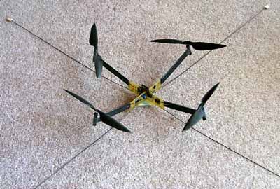
Rotary Wing Flyer Version One
The flyer, shown below, is essentially a flying printed circuit board. The thin, light, 20mil circuit board also serves as the frame to which the motors are attached with CA glue. The connector for the battery is also the battery support post. The PIC17 micro-controller can easily be extended with additional sensory and communication components as well as additional control software to incorporate their functionality. The surface mount PIC17 reads the incoming motor controls from the Linx Technologies 418MHz receiver via a serial digital interface and one of the PIC17’s two UARTs. The PIC17 uses its 3 on-chip PWM outputs plus a fourth PWM, implemented in software using timers, to drive the motors. L293DD power chips input the PWM and deliver 1.2A (max) of current to each motor. The vehicle with motors and battery weighs 65 grams and generates 80 g of total thrust. The PIC17 software is written in C giving the capability for expansion through use of the 12 10bit A/D inputs, I2C interface, dual UARTs, pulse width modulators, and many robust I/O pins.
Vision Stabilization
The flyer has been tested and it lifts off and flies. However, it is very difficult to control without some form of sensor based stabilization. An investigation is underway into the use of a CMOS image sensor and fixed lens as input into a vision stabilization system. The Photobit PB0100 CMOS camera chip has been selected for its flexible register control, dynamic on-chip exposure control, and convenient I2C interface to the PIC17 micro-controller. The PIC17 and 4800 baud radio are not fast enough to communicate video to an image processor on the ground but initial calculations indicate that the PIC17 is fast enough to sample small regions of the camera image and to compute the optical flow vectors for these regions. These vectors will be used to compute an estimation of the six degree-of-freedom spatial vector describing the vehicle motion. This sensed motion will be used to stabilize the vehicle.
The PB0100 chip is shown below on the PCB for the new vision stabilized flyer. The lens in its black plastic lens holder and the PCB for the camera are also shown.
Simulator for Vision Stabilization
A simulator is under construction that will facilitate the testing of various algorithms and parameters in vision stabilization. The simulator will include a rigid body dynamic simulation of the flyer, a geometric model of the camera, an anti-aliased ray tracer for sampling the image that the camera sees, a visual environment consisting of a texture mapped ground plane, and a motion estimation and feedback control system.
The rigid body dynamic model of the flyer is given by the following Newton Euler equation of motion using spatial vector notation.
Modeling the motors as point masses on the x and z axis of the body fixed coordinate frame having its origin at the center of mass, and modeling the battery as a point mass on the –y axis, gives the following inertia tensor.
where mi is total flyer mass, si is the vector to the center of mass and is equal to zero, d is the distance to each motor, l is the distance to the battery, mk is the mass of a motor, bk is the mass of the battery, and a is the spatial acceleration. The spatial force fi is the sum of the forces acting on the flyer including rotor lift forces, drag forces (torques), gravity, and noise.
Here q is the inward tilt angle of the motor thrust line of force, and k relates drag torques to thrust as a linear approximation. The spatial acceleration is obtained by multiplying the inverse of the constant 6x6 diagonal inertia matrix II times fi.
Spatial velocity is computed by integrating the acceleration.
Spatial position, using a quaternion to represent angular orientation, is
computed by integrating the linear velocity to get the position, and by
computing a difference quaternion for the orientation. The difference quaternion
being ![]() and the
associated incremental rotation matrix is
and the
associated incremental rotation matrix is![]() where w
is angular velocity, qe = <qe0 qe1
qe2>, E is the identity matrix, and | qe0
qe1 qe2 qe3 | = 1.
where w
is angular velocity, qe = <qe0 qe1
qe2>, E is the identity matrix, and | qe0
qe1 qe2 qe3 | = 1.
The camera model comprises a center of projection COP expressed in the body fixed frame, a direction vector, an up vector and a region in the view plane. This geometry determines the rays to be traced to obtain the pixel data. Anti-aliasing is done by casting rays through the corners of pixels, finding their intersections with environment textures, then averaging the texture regions using a quad-tree. The pixel data is used in the following optical flow equation due to Berthold Horn 1986 and made rigorous by Oliver Faugeras 1996.
![]() This equation expresses the assumption that in any small region of the image and
within a small step of time, only a translation of the image will occur. Here I
is the image as a function of x, y, and t, and V=<u,v> is the velocity of
the translation in image space. Since we can compute the spatial gradient of the
image and the time derivative from the pixels, this gives one equation with two
unknowns. Additional information needed to solve this comes from a smoothness
assumption, giving the following optical flow algorithm for computing V.
This equation expresses the assumption that in any small region of the image and
within a small step of time, only a translation of the image will occur. Here I
is the image as a function of x, y, and t, and V=<u,v> is the velocity of
the translation in image space. Since we can compute the spatial gradient of the
image and the time derivative from the pixels, this gives one equation with two
unknowns. Additional information needed to solve this comes from a smoothness
assumption, giving the following optical flow algorithm for computing V.
u = uav - Ix P/D P = Ixuav + Iyvav + It
v = vav - Iy P/D D = l 2 + Ix2 + Iy2
where Ix is ¶ I/¶ x, and uav is a spatial or temporal running average of u.
The simulator will explore several control and feedback mechanisms for stabilization using these optical flow vectors. The resulting algorithm will be tested in the prototype flyer.
PCB Flyer Version Two
The version two flyer adds three rate gyro sensors and uses Astroflight firefly motors with 16:1 gearboxes turning ten inch propellers at about 2000 rpm and designed for hovering flight. Stabilization is performed using a PID algorithm with integrator washout to eliminate integrator error due to the accumulation of noise. The PID coefficients KP, KD, KI, and the washout coefficient KW are transmitted from the ground transmitter to the flyer so that the PID gains can be adjusted from the ground PIC. The ground PIC17 is also reprogrammable. Here is a view of the flyer showing long carbon rod legs that provided stability during initial flight testing.
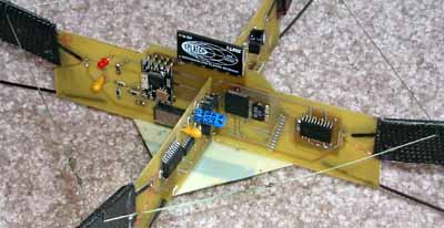
So far this flyer has only been flown loosely tethered. It appears so far to behave with good stability. We have had some problems with the solder contacts of the 64 pin PIC17 chip. Initial flight problems caused the circuit board to flex and loosen some contacts. Since then the vibration and stress of normal flying has on several occasions caused a connection to go bad. Resoldering fixes it for a while. I think the initial soldering must be well fluxed and well soldered and the frame must be braced to minimize circuit board flexing. Here is a close up view of the central part of the flyer.
Fabrication Details
This section details the tools and methods used to build the flyer. The emphasis has been on low cost readily available tools and components.
Schematics and Layout
The Ivex Design International (http://www.ivex.com/) WinDraft software was used for schematic design and WinBoard was used for board layout. The transmitter circuit is
where the PIC is running at 32MHz with an external oscillator. The PIC uses it’s A/D inputs to sample the joystick potentiometers for roll, pitch, yaw, and throttle. The LM324M is for impedance matching. The LED array is used for debugging display, and the PIC serial output TX2 is used to send data to the transmitter. A 9V battery supplies power through the 5V regulator. The radio is available from Linx Technologies (http://www.linxtechnologies.com)/, the Microchip (http://www.microchip.com/) PIC chips are available from Digikey (http://www.digikey.com/ ) or Future (http://www.futureelectronics.com)/, and the LM324 OpAmp from Pioneer (http://www.pios.com/ ). The other parts can be found at a good electronics store or Digikey. The oscillator: XC631CT-ND crystal 32.000MHZ SER FUND SMD is available from Digikey.
The circuit for the flyer is
where the three ENC-03J Murata rate gyros have RC bandpass filters that limit the rate gyro frequency response between 800Hz and 0.3Hz. The rate gyros signal is amplified by the LM324M Op Amp whose output then goes to the A/D inputs of the PIC17. The PIC uses its serial input port RX2 to receive data from the RX-418-LC Linx radio receiver. This data contains motor drive values, button values, and PID coefficients for the rate gyro, feedback stabilization, algorithm sent from the ground transmitter. The PIC then uses its pulse width modulation outputs to drive the two L293DD power chips which provide current to the four motors. The 10K pulldown resistors on the PWM outputs from the PIC ensure that the power chips are turned off during PIC reboot or brownout.
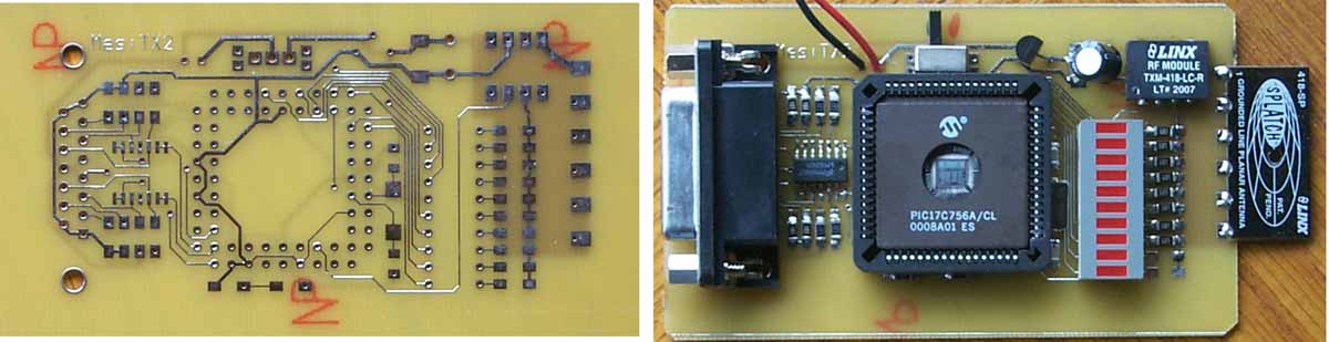
The IVEX WinBoard software takes the netlist output from the IVEX WinDraft software and is used to layout the prototype boards. WinBoard generates the gerber plots, the drill files and other files needed to specify the board. This set of files were sent to Alberta Printed Circuits (http://www.apcircuits.com/), a company in Canada that gives two day delivery of prototype boards. Here is the transmitter board before and after stuffing the chips. Surface mount components are used wherever possible.
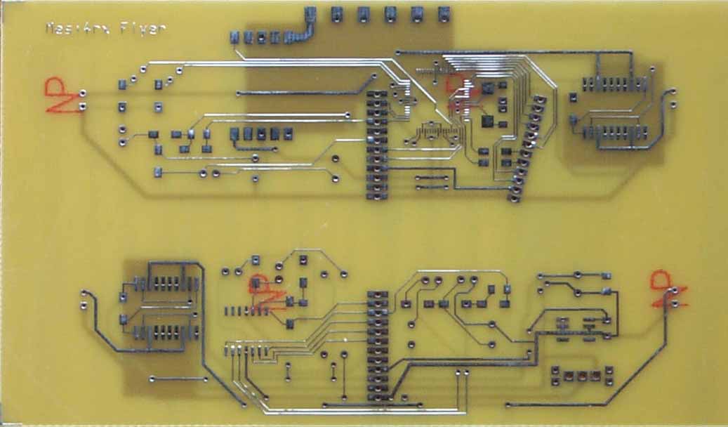
 The flyer boards shown below have a "bus" at the center, that is
slotted so the two boards can form an X shaped frame for the flyer. The version
shown also contains circuitry for an onboard camera.
The flyer boards shown below have a "bus" at the center, that is
slotted so the two boards can form an X shaped frame for the flyer. The version
shown also contains circuitry for an onboard camera.
Software
Software development on the PIC can be done using the C programming language. A demo compiler, MPLAB-C17 Demo v2.30.04, can be downloaded from the Microchip web site. The MPLAB development environment software and the inexpensive PICSTART Plus development programmer allow for code development and for downloading the code to the chips via a serial port on a PC. A UV Eraser (model QUV-T8) from Logical Devices Inc. can be used to erase the program from the /CL PIC chip when changes need to be made. The /PT surface mount PIC is one time programmable. The proper sockets for the PICSTART Plus must be used to program the /CL and /PT PIC chips. For the /PT use the PA756-64Q programming adapter, a 64pin QFP socket to 40 pin 0.6" DIP plug from http://www.logicalsys.com/. For the /CL use the 68P PLCC adapter socket from Microchip - part #AC164024.